Pedalboard MIDI Controller
a MIDI VPO Controller
Overview
A virtual pipe organ (VPO) can recreate the capabilities and sound of a traditional organ through extensive sample libraries controlled by Musical Instrument Device Interface (MIDI) controllers. In this project I overhauled an organ pedalboard to update its sensors and allow it to communicate over MIDI. I additionally outfitted an expression pedal for MIDI communication and integrated it, the pedalboard, and three keyboards into a VPO setup. Following the overhaul in 2021, I revisited the design in 2023 and again in 2025 to streamline the system.
Design
2021 Design
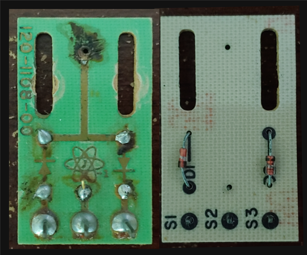
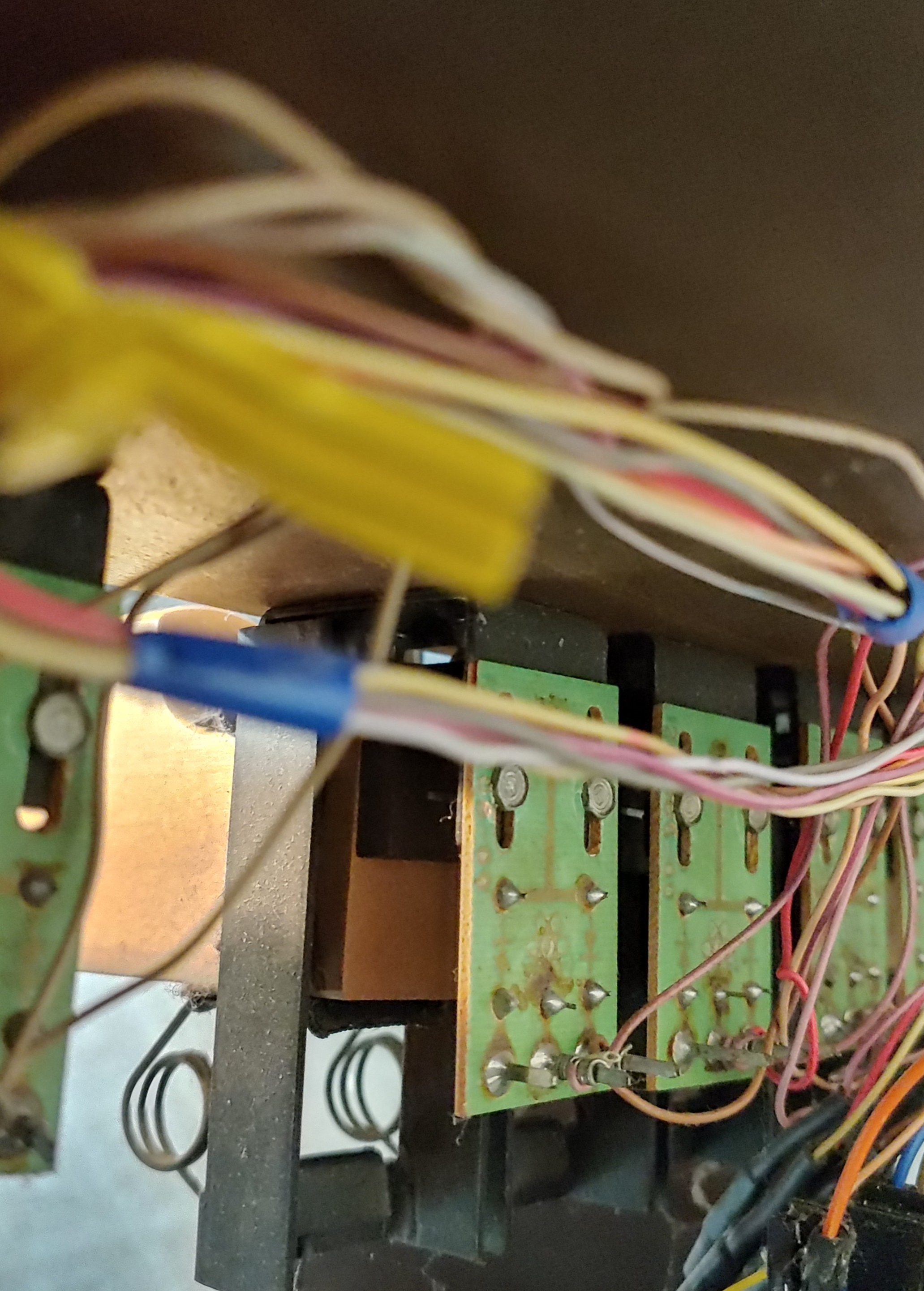
The pedalboard contains 32 pedals, each of which has a magnet attached to its toe end. In front of each magnet a bracket suspended a 1” by 1.7” PCB with approximately 0.615” long slots for adjusting the pedal depression threshold for switching notes. In the pedalboard’s original design, each of these sensor boards housed a reed switch and two diodes. Three pins at the bottom of each board provided the connection points for harnessing, which gathered the signals from the 32 boards to be provided to the organ’s original console.

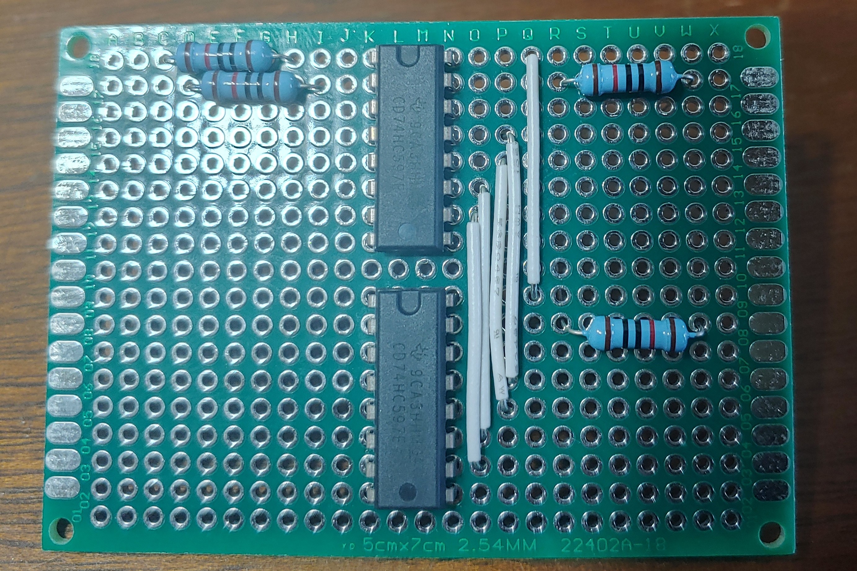
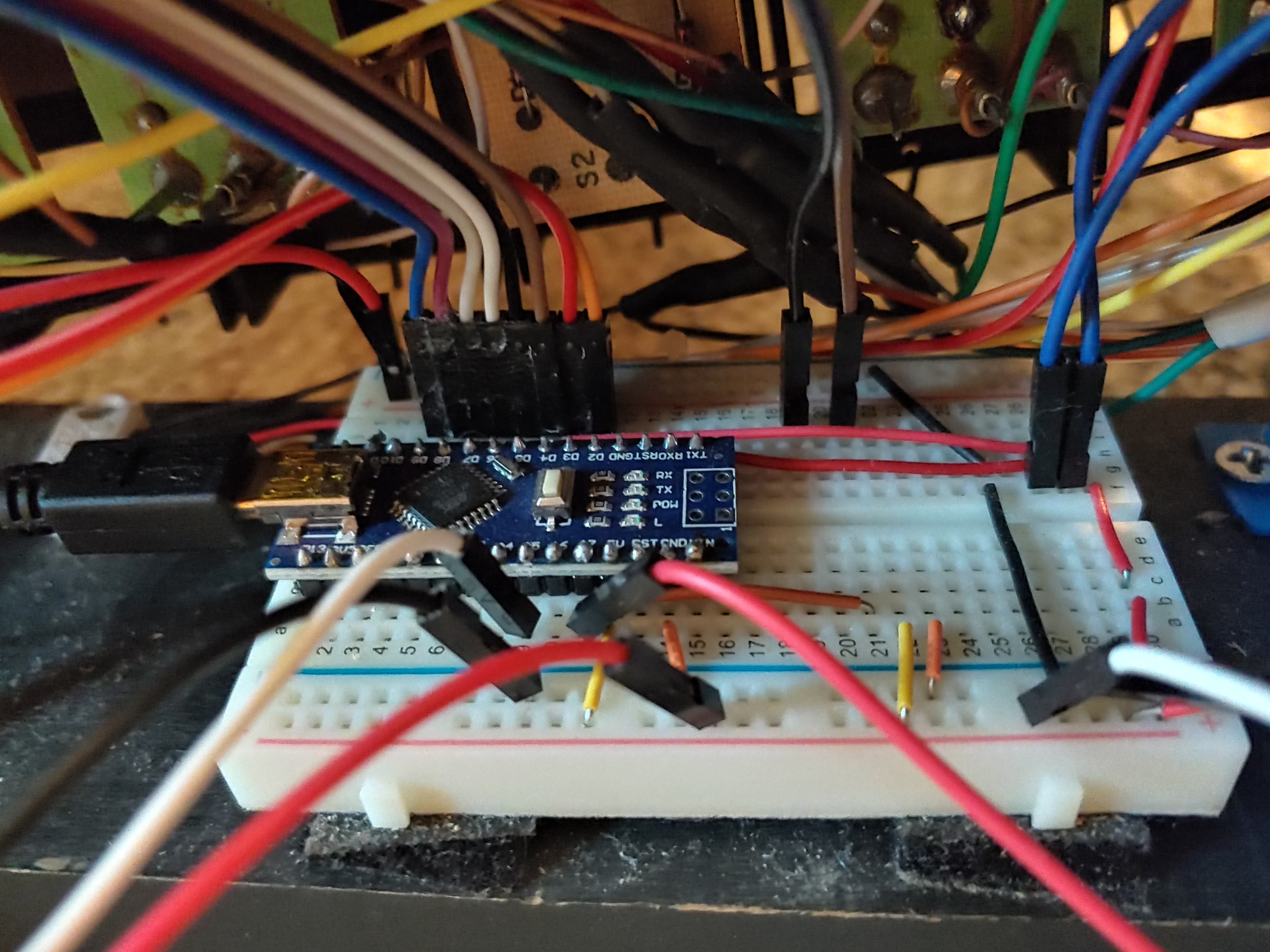
Without the console, the overhauled version of the sensor boards were to communicate with an Arduino which generated MIDI messages from pedal presses. The 32 inputs would be sent to four 8-bit parallel-in, serial-out shift registers to reduce I/O requirements on the Arduino. The shift registers were housed on a pair of protoboards alongside 10K pull-down resistors for the inputs. In the 2021 overhaul, the sensor board hardware was reused without alterations. Two of the three pins on these boards were used, with one providing a logic high connection to pull up an output pin. Each of the shift register boards was wired to a breadboard housing the Arduino. This breadboard also accepted a connection from the expression pedal to be read by an Arduino analog input.
An Arduino Nano served as the pedalboard’s controller. It produced the control signals for the shift registers, maintained an array representing the states of pedals, tracked the expression pedal’s volume, and output MIDI messages. Each message consisted of three bytes: a command byte and two data bytes. For the pedals the command byte was either a “note on” or “note off” command. The first data byte was a pitch number, and the second a velocity. Organ pedals are velocity insensitive, so an arbitrary value was output. For the expression pedal the command byte was a “control change” command. The first data byte identified the controller as an expression pedal and the second was the pedal’s value quantized to 7 bits.
, and signals from two expression pedals (near side of Arduino)")
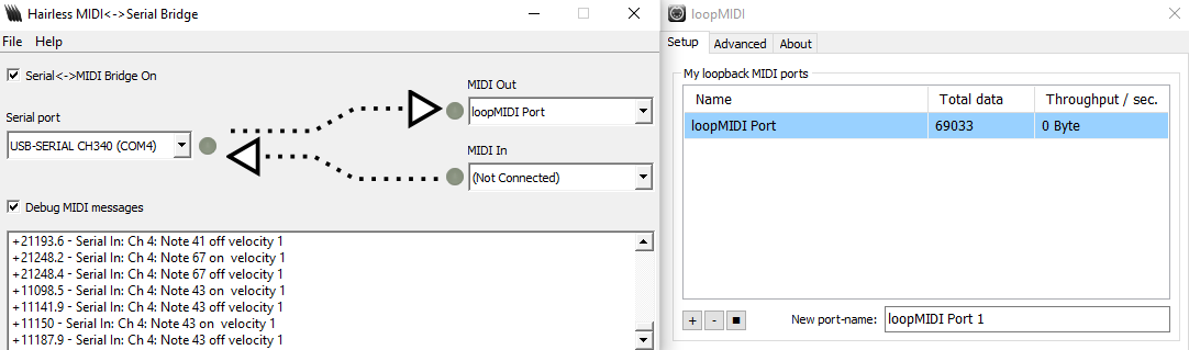
The Arduino is recognized by Windows as a generic COM port device. I used The Hairless MIDI to Serial Bridge to open a MIDI port carrying these messages and loopMIDI to create a virtual MIDI loopback port, which allowed VPO programs to recognize and connect to the port. A USB midi interface was responsible for combining messages from three keyboards with built-in MIDI capabilities over a second MIDI port.

2023 Update
The reed switches were quite fragile, leading to several needing replacement in the original overhaul and a small number needing replacement in the intervening two years. The dependence of the sensor boards’ thresholds on their mounting height additionally inconvenienced installation and encouraged intermittent servicing if any were to slip. I addressed both shortcomings with a design replacing the reed switches with hall effect sensors.
The design used a hall effect sensor with PWM output corresponding to magnetic field strength. The output was averaged through an RC network and passed to a comparator with its reference voltage taken from a potentiometer for electronic threshold adjustment. The comparator was given some hysteresis to mitigate instability caused by ripple in the averaged PWM signal.

2025 Update
In this most recent update I hope to address the large number of wires which run from the sensor boards to the shift registers using a bus.
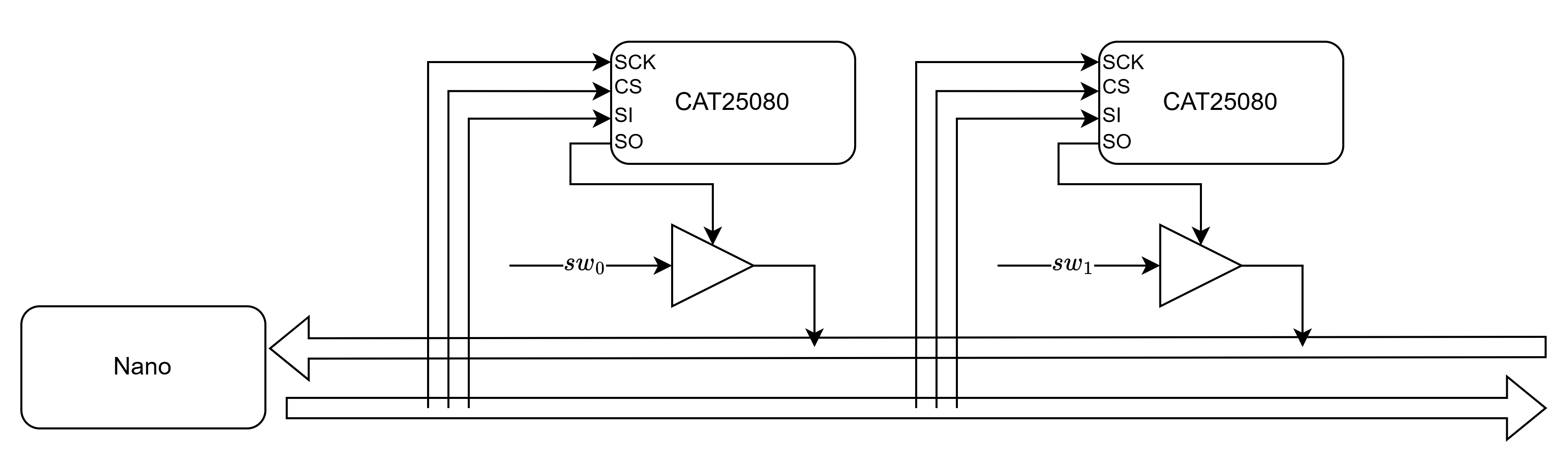
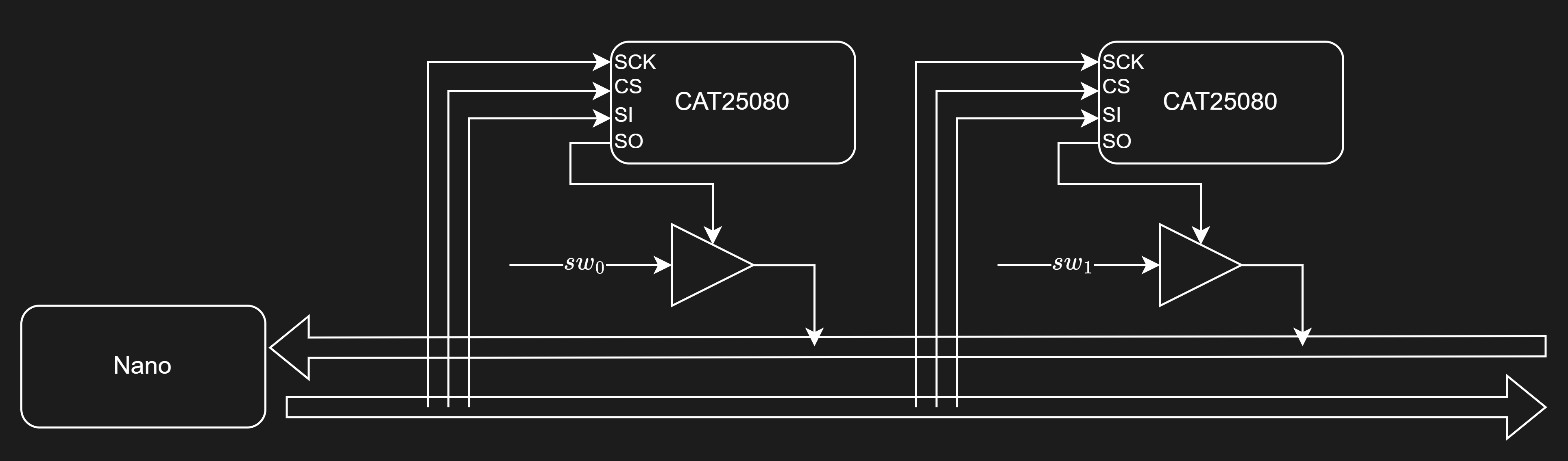
Unable to identify a suitable IC for transmitting the sensor boards’ single bit outputs over a serial protocol or a reasonably priced hall effect sensor with bus protocol communication, I decided to use memory ICs as a vehicle for placing the sensor boards on a bus. On each sensor board, a small memory with serial output can be used to generate the enable signal for a tri state buffer. The memories can then be programmed such that only one buffer is enabled on each data wire in the bus in a given clock cycle when all memories are read simultaneously.


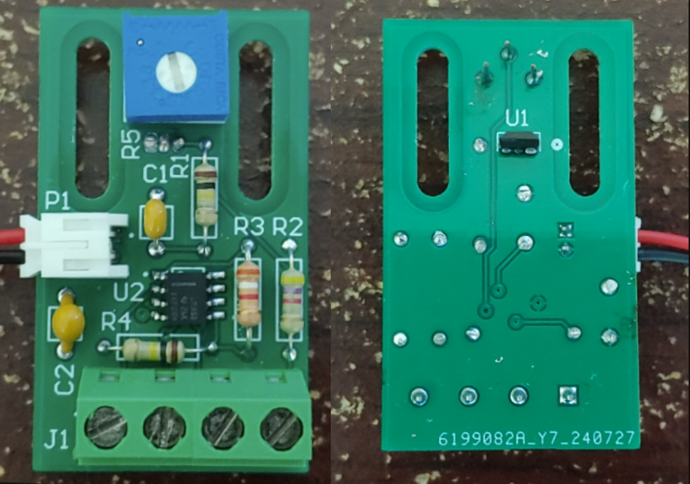
I made additional modifications to the sensor side of the circuit. The PWM hall sensor was replaced with one that produces an analog output directly, and the averaging RC network was removed. A dual op-amp which served as a unity gain buffer and comparator was replaced with a single comparator which drives the tri state buffer. A small output resistor was added after the tri state buffer to limit current in the case of bus contention. The bus was implemented in the board’s layout with a single insulation displacement contact connector on each board. Through hole components were replaced with surface mount ones to facilitate placement underneath the bus wires.

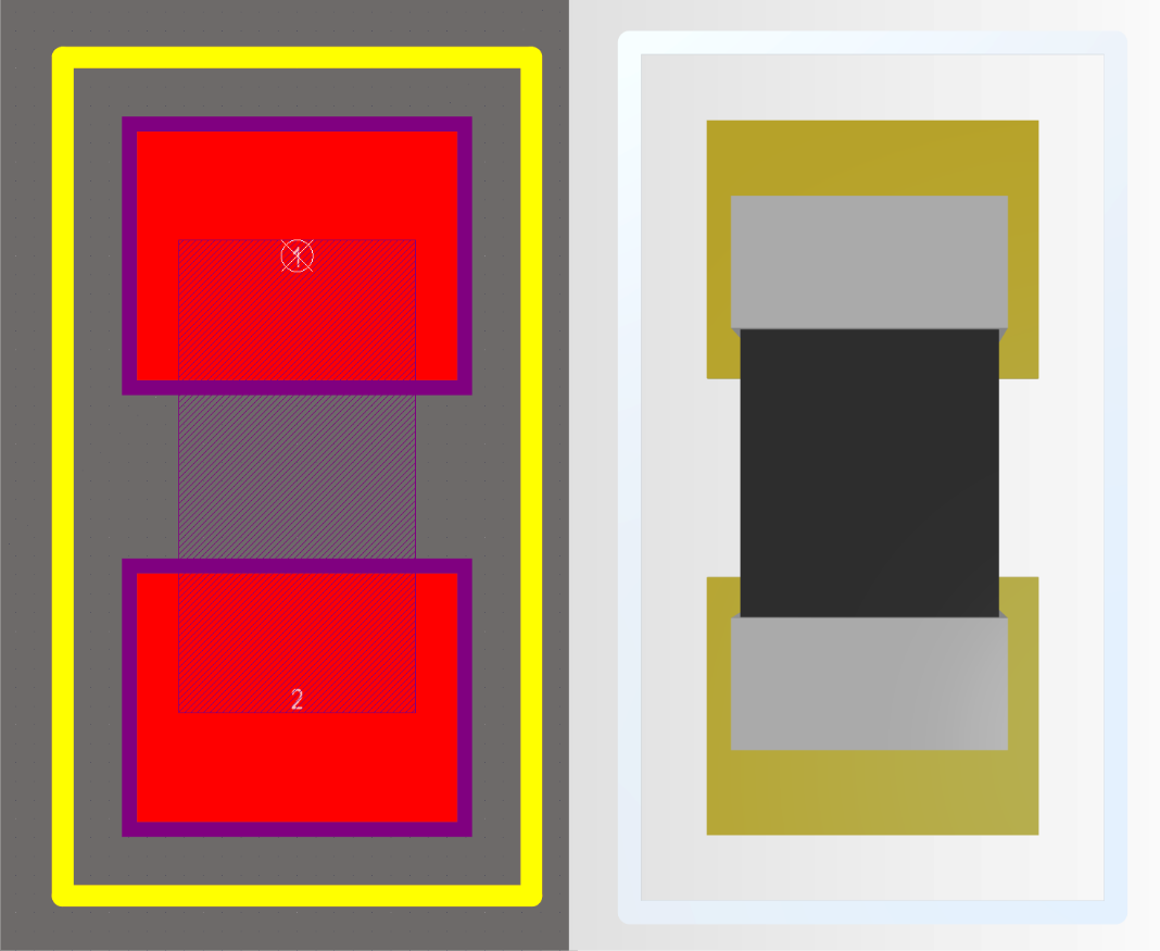
The layout for this revision of the board has been finalized and fabricated. Current efforts are devoted to sourcing parts for assembly.