CaliPER Control System
a CubeSat controller
Overview
My senior capstone design project extended a prior design exercise toward the development of a prototype cube satellite (CubeSat). The CubeSat was designed with the necessary capabilities to characterize the REASON radar antenna aboard NASA JPL’s Europa Clipper during its transit to Europa. I was responsible for designing a control system that uses Guidance, Navigation, and Control (GNC) sensors, and a warm gas propulsion system to guide the CubeSat to commanded positions and orientations relative to Clipper. During the project I had the pleasure of working alongside 11 of my peers across various engineering disciplines and receiving the mentorship of JPL’s Adrian Arteaga Garcia.
Background
The Europa Clipper space probe launched in 2024. Among several instruments, it is equipped with the Radar for Europa Assessment and Sounding: Ocean to Near-surface (REASON). The multi frequency radar was designed to measure the depth of ice below Europa’s crust, as well as the depth of any potential bodies of water beneath the ice.
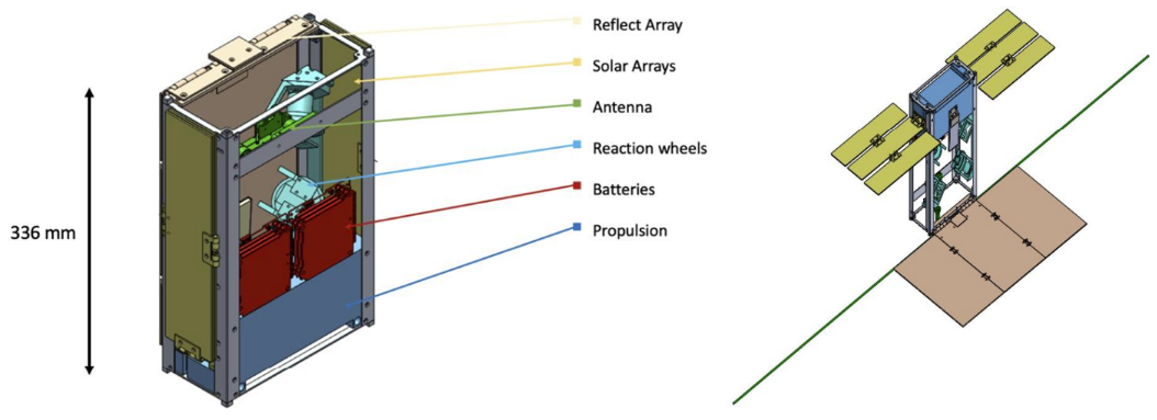
In order to interpret radar sounding measurements, REASON’s beam pattern must be accurately characterized. Clipper’s deployed length of over 30m and REASON’s antenna length of about 16m impede characterization on Earth. The process would require both a large test chamber in which the RF signal could be isolated, and a method to combat deformation of the antenna under earth’s gravity. A small and more easily maneuverable CubeSat which would fly through REASON’s beam pattern en route to Europa was proposed as a characterization solution. In 2022 a group of Harvard engineering students began the design of the Calibration Post Earth of Reason (CaliPER) CubeSat, as a pedagogical exercise. In 2023, another team of students carried out the work of redesigning CaliPER for a 6U form factor (half the volume of the original 12U design). This team additionally prototyped a warm gas propulsion system, a GNC actuator and sensor suite, an RF antenna and deployment system, solar and reflect array systems, and a bus structure which housed all of the CubeSat’s subsystems.

Design
The GNC hardware sensor suite consisted of an inertial measurement unit (IMU) and star tracker. Additional position and velocity information, as well as commands driving the mission phase would be sent intermittently from NASA’s Deep Space Network (DSN). Data from these sources informed the controller’s actuation of a set of 4 reaction wheels (RWs) in the GNC system, and 8 thrust control solenoid valves in the propulsion system.


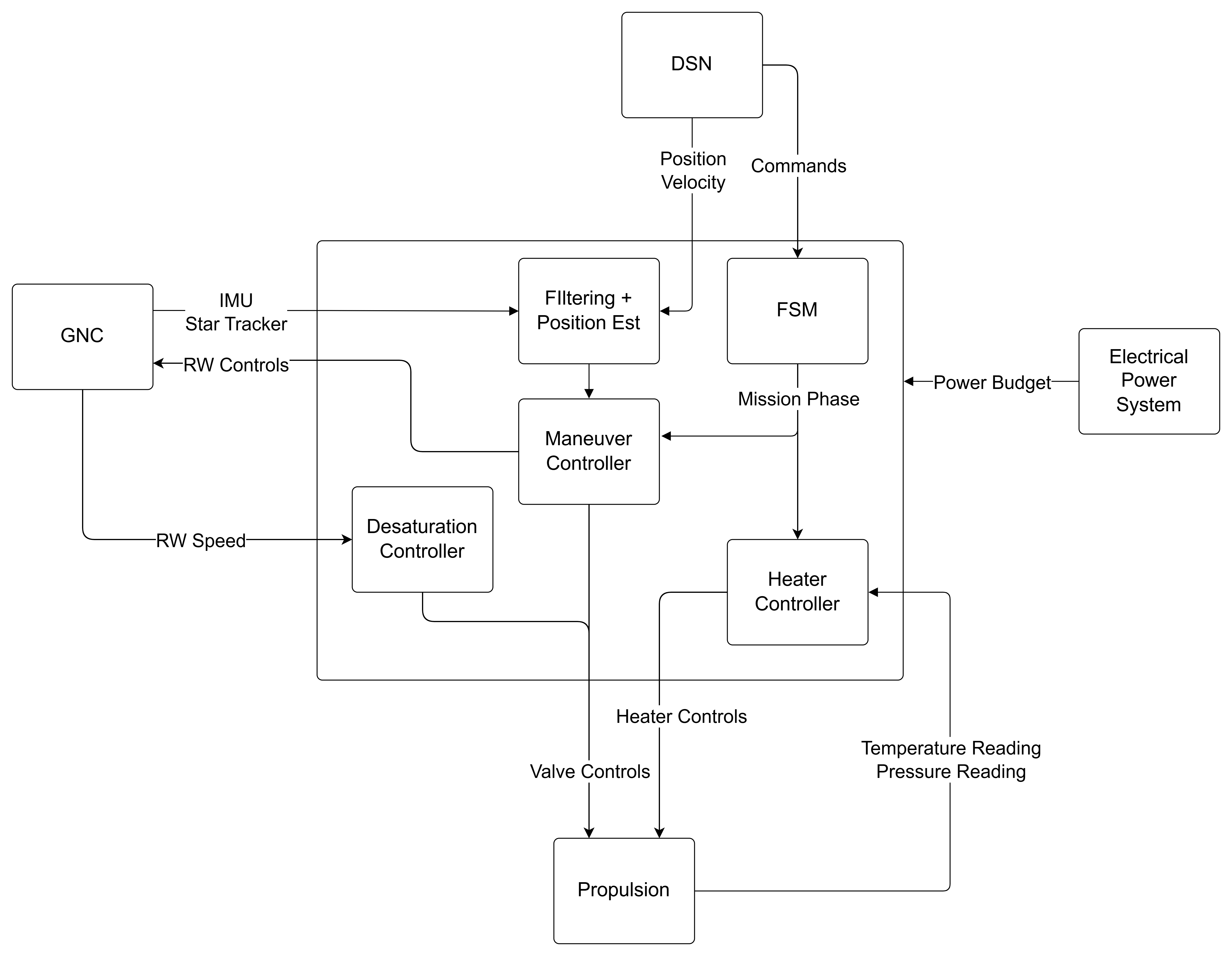
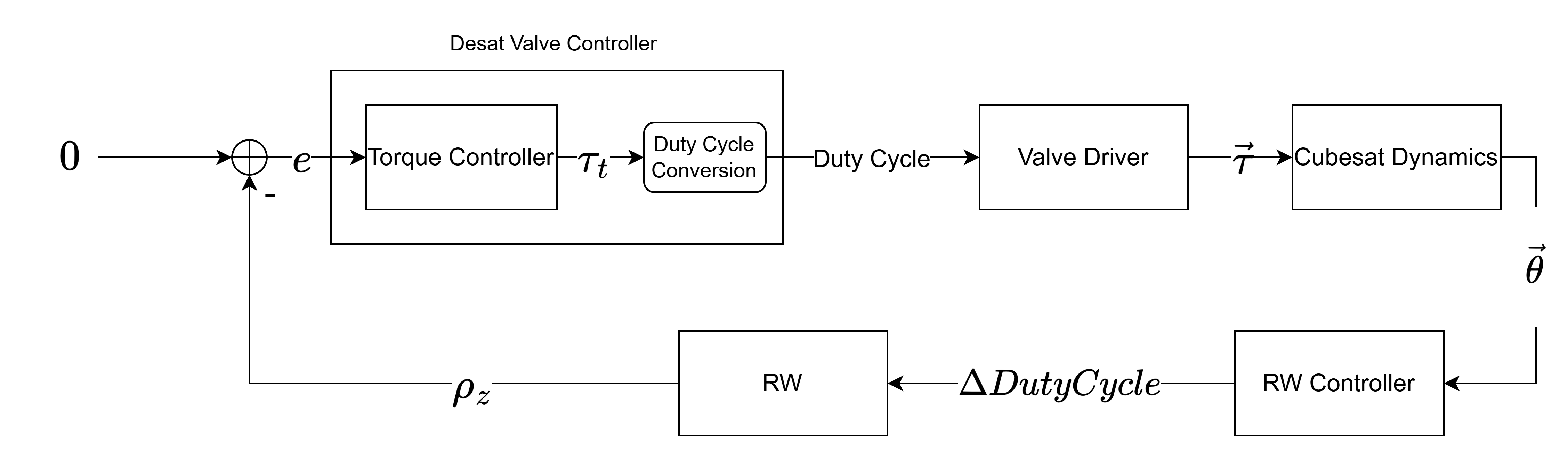
The control system was composed of three controllers responsible for maneuvering, desaturation, and propellant temperature control. A control loop and hardware supporting the temperature controller were designed; however, due to time constraints this controller was not implemented.
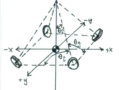
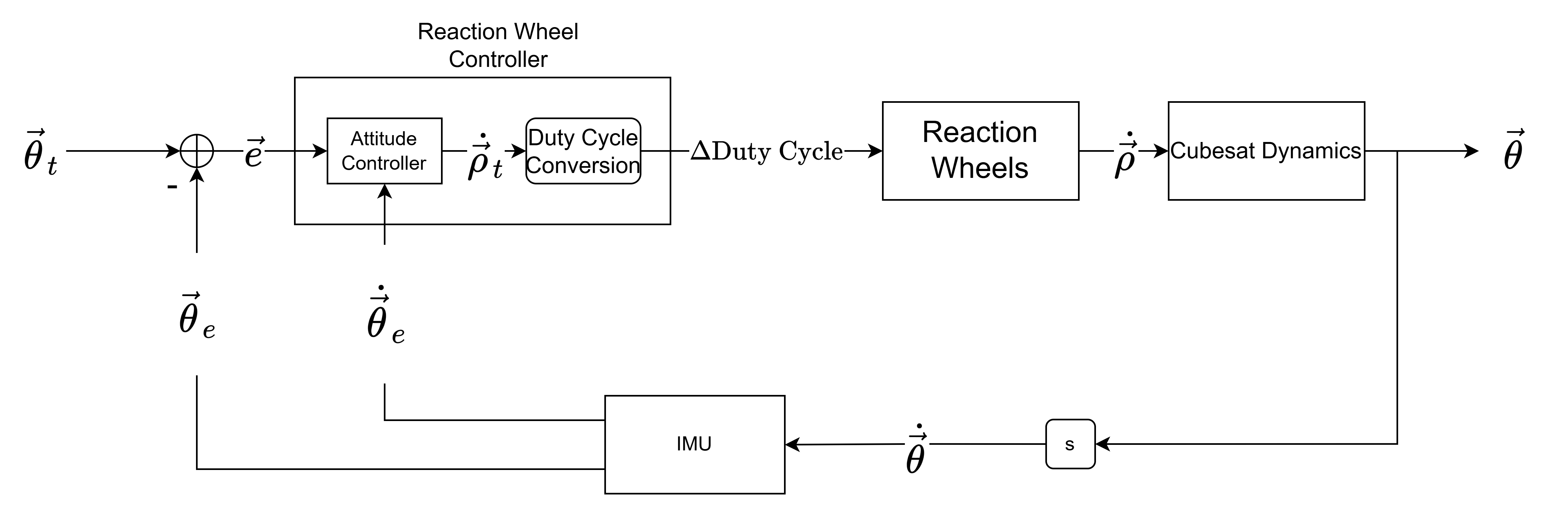
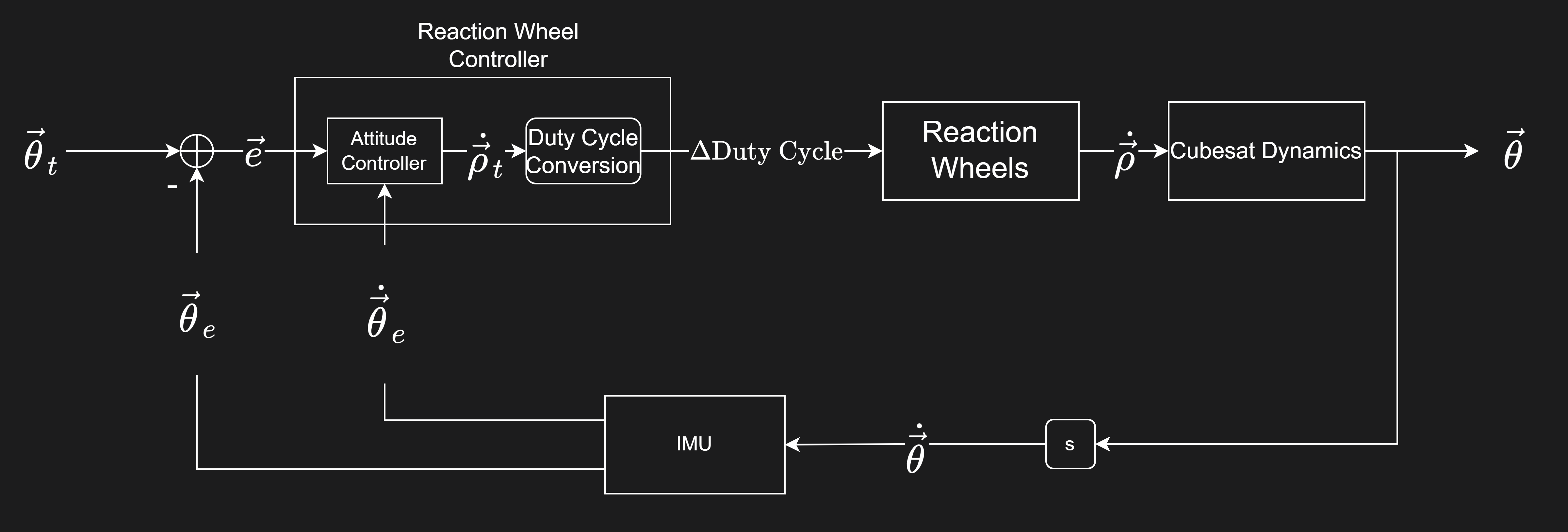
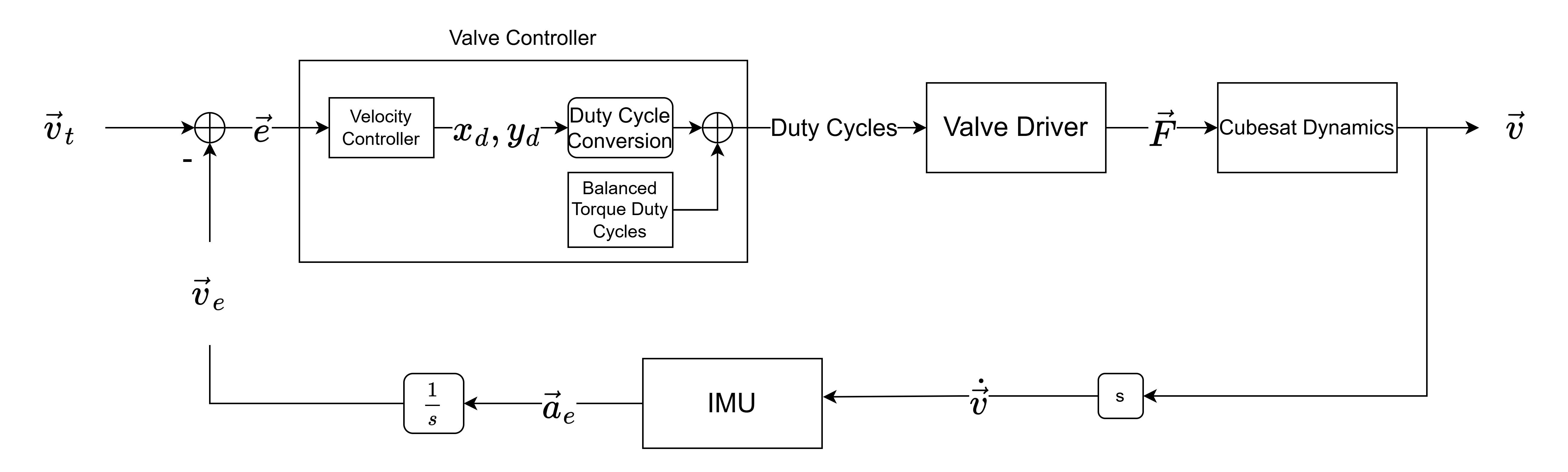
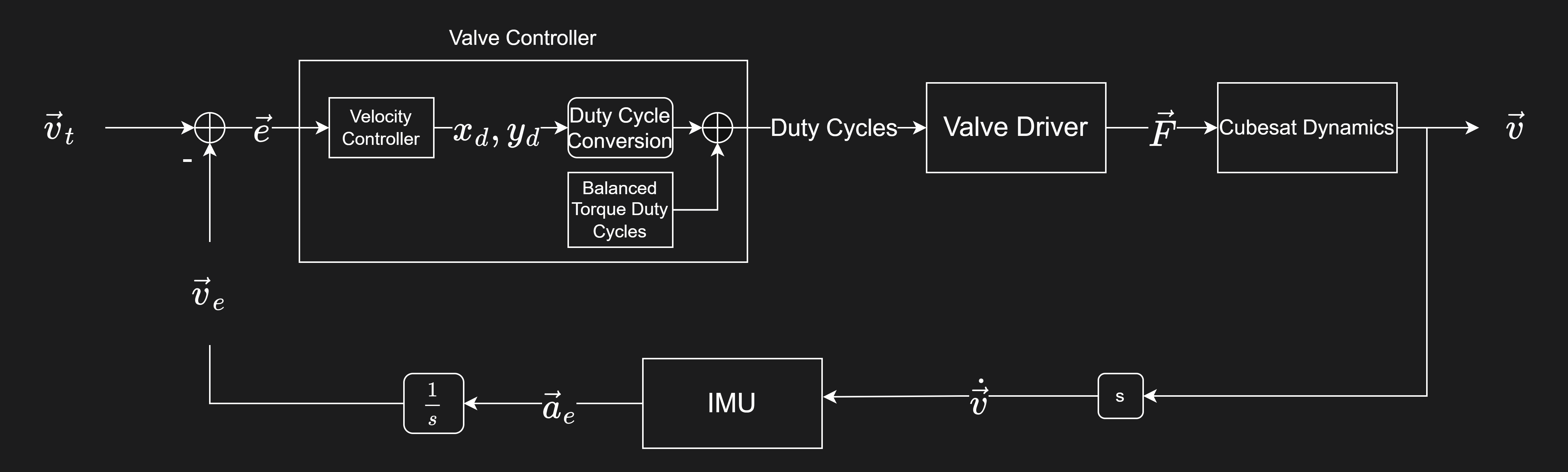
In the context of chasing Clipper and moving through a calibration trajectory, maneuvering consists of translating CaliPER relative to Clipper and controlling the orientation of CaliPER’s reflect array relative to Clipper. The maneuvering controller was analogously divided into a translation controller and a slewing controller. The slewing controller engages the RWs to achieve or maintain a target orientation. The translation controller engages the thrusters to achieve a target velocity. As a result of the thruster configuration, CaliPER can only be propelled in the Z direction without experiencing a torque. Translation in an arbitrary direction involves activation of the slewing controller to align the Z-axis with the direction of travel prior to activating the translation controller.

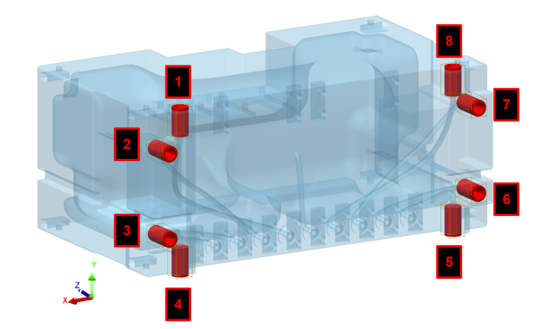
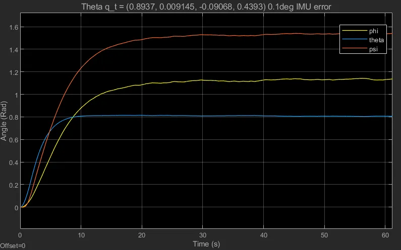
CaliPER would experience a number of torques throughout the duration of its mission including a tip off torque on release and several environmental torques while in transit. CaliPER would accumulate angular momentum under these torques, which would be transferred to the RWs when maintaining an attitude. The desaturation controller is responsible for engaging the thrusters to dump accumulated angular momentum, such that the RWs do not reach their saturation point for the duration of the mission. As a result of their configuration, the thrusters can only generate torque about the Z-axis without generating a net force. Desaturation of the RWs involves dumping angular momentum in the Z-direction and subsequently slewing to align the body Z-axis with the initial Y and X axes to dump angular momentum in these directions.

CaliPER’s warm gas propulsion system was designed with a polyimide element to heat propellant in preparation for thruster activation. The temperature controller is responsible for activating the element and preheating to a 30°C set point before initiating burns. The controller receives data from a resistive temperature device and pressure sensor in the propulsion system to ensure temperature tracking and prevent an overpressure condition.
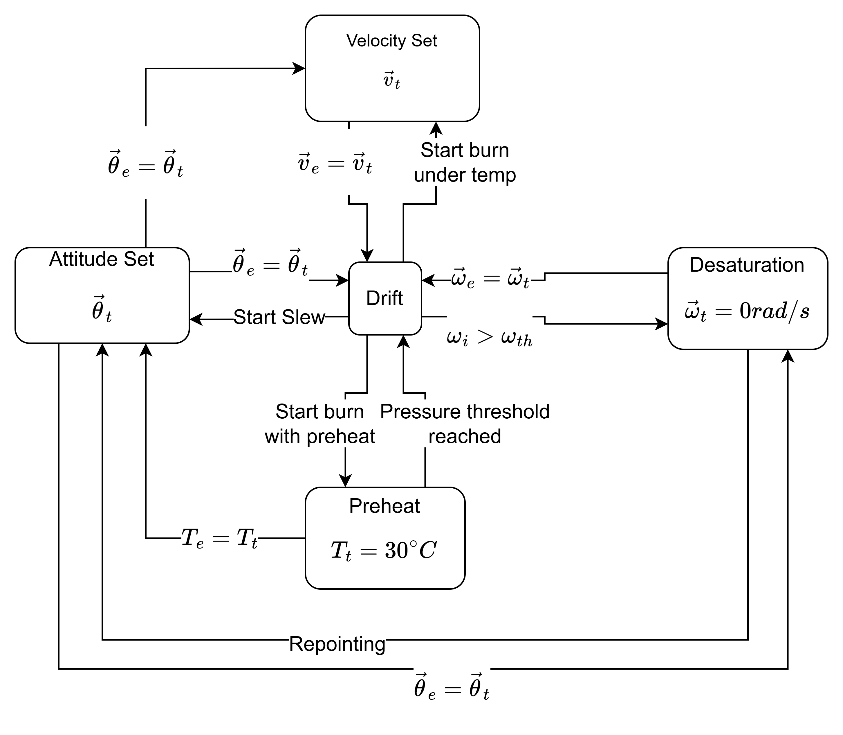
A finite state machine (FSM) guides CaliPER through the abovementioned steps for preheat, maneuvering, and desaturation. In the context of Clipper’s mission, CaliPER would be equipped with a local copy of the mission phases through this FSM, as well as states to respond to high level ground control commands like trajectory control maneuvers.


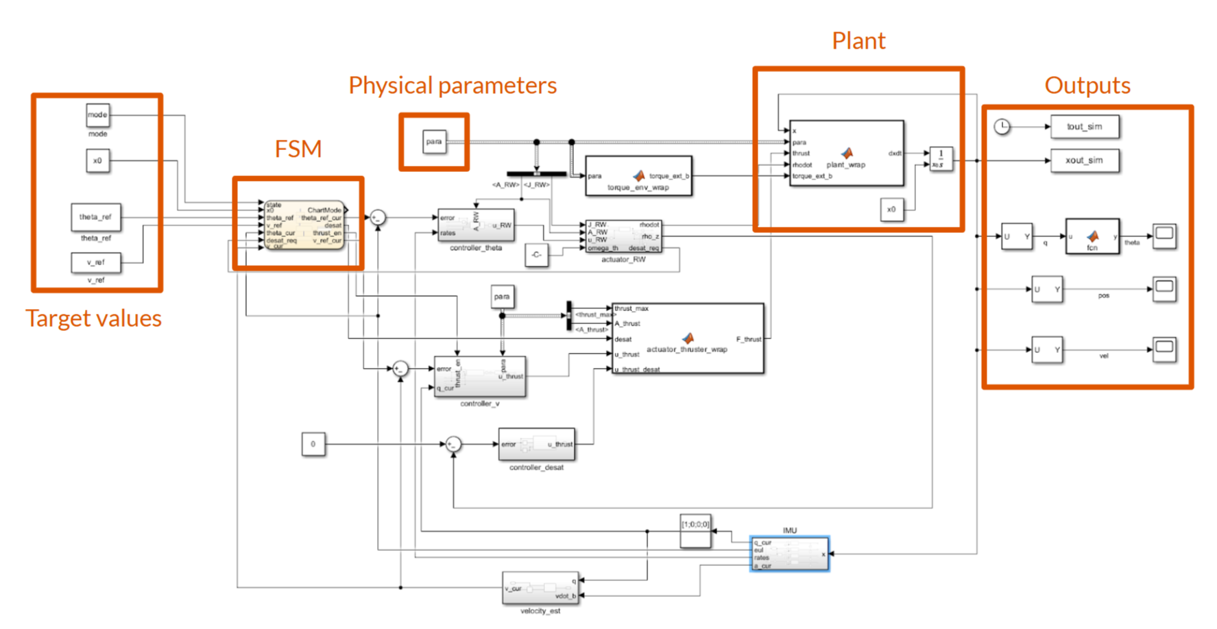
The maneuvering and desaturation controllers were tested in a Simulink rigid body simulation using the physical properties CaliPER was designed to have: its mass, inertia tensor, thruster locations, thrust forces, RW cants, and RW induced torques. In addition to plant and actuator blocks, the simulation included sensor blocks simulating the IMU’s bandwidth, error, velocity estimation procedure, and body rate estimation procedure.

Four versions of the slewing controller were iteratively designed and tested, the final of which was a development of a PD controller. The RW induced torque was determined by a proportional term based on the error of the vector part of the attitude quaternion, and a derivative term based on the body angular velocity. This torque was finally converted to the 4 RWs’ duty cycles through the pseudoinverse of the matrix describing their cants.


Three versions of the translation controller were designed. The controller’s final version calculated the thrust necessary in each of the Z-axial thrusters to produce translation without torque given a specified center of mass. The controller also incorporated proportional thrust terms for differentially activating the Z-axial thrusters to suppress turning in the X and Y directions. These additional terms help mitigate center of mass offset, thruster misalignment, and thruster imbalances due to manufacturing tolerances. The closed loop terms also combat dynamic center of mass changes caused by conditions like fuel sloshing.


The desaturation controller was implemented as a proportional controller producing duty cycles for either thrusters 1 and 5, or thrusters 4 and 8 depending on the sign of the required desaturation torque. During desaturation, the slewing controller must also be active such that the RWs reduce their angular momentum while maintaining an attitude under the thruster torque.


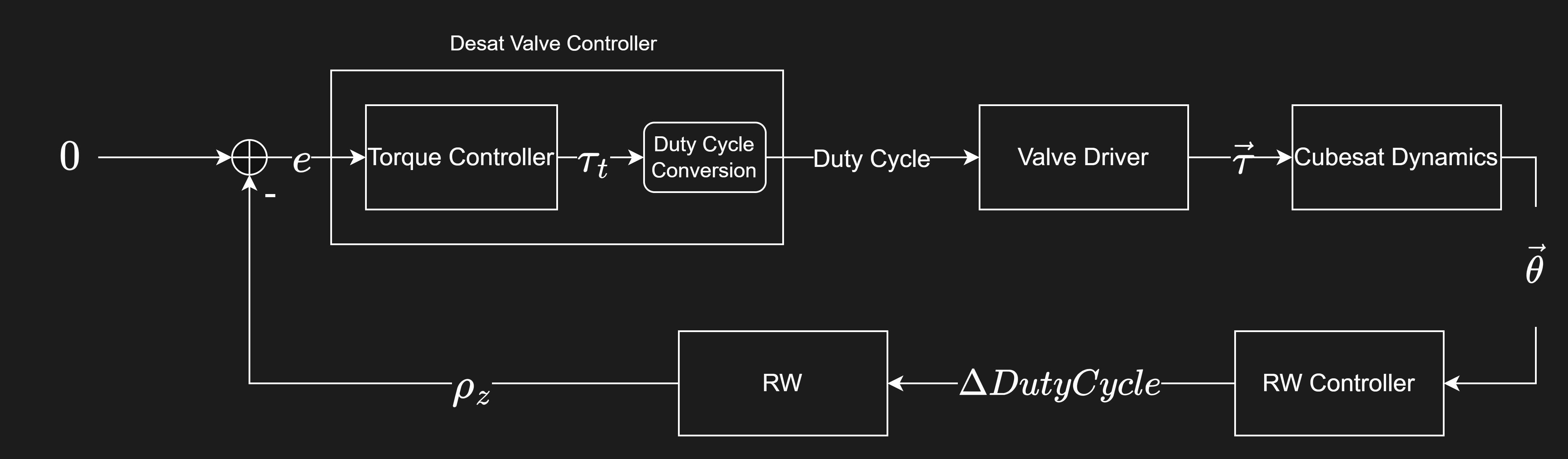
Tests of the maneuvering controller were comprised of repointing to 10 random attitudes for the slewing controller, and stepping the target velocity to 5 random velocities for the translation controller. The test velocities were chosen to have components between 0 and 6m/s, matching CaliPER’s planned calibration trajectory. To test the desaturation controller, torques with magnitude 0.05Nm were applied to CaliPER, triggering desaturation. The sign of the torque components were varied over 5 trials.

Of the 8 technical specifications set out for the design, 4 were met in the simulation, 3 required further testing, and 1 was not met. A discussion on the paths to verification, and impact on CaliPER’s mission is offered in the technical report. Further detail on the controllers, Simulink components, and design and test methodologies can be found there as well.
References
2023
- CubeSat Bus for CaliPER Mission in Support of Europa Clipper2023
- Design of the Calibration Trajectory and 3D-Printed Warm Gas Propulsion System for an Auxiliary CubeSat for the NASA JPL Europa Clipper Mission2023
- Machining and Optimizing a GNC Subsystem for the CaliPER Calibration Satellite of Europa Clipper2023